4 min to read
How to Make L293D Motor Driver Module
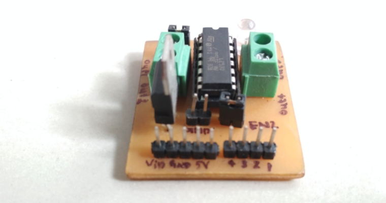
Homemade L293D motor driver module
This is a first post on my blog. In this blog I am trying explain how to make a L293D motor driver module at home.
Components required
- L293D IC ×1
- 16 pin IC base
- 2×1 Screw terminal × 2
- 2×1 male header pin × 2
- 7805 voltage regulator
- LED
- 1K Resistor
- Small piece of Breadboard
About L293D IC
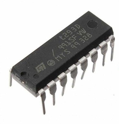 L293D is the main part of the project. The L293D devices are quadruple high-current half-H drivers. The L293D is designed to provide bidirectional drive currents of up to 600-mA at voltages from 4.5 V to 36 V.
L293D is a 16-pin IC which can control a set of two DC motors simultaneously in any direction. It means that you can control two DC Motor with a single L293D IC.
L293D is the main part of the project. The L293D devices are quadruple high-current half-H drivers. The L293D is designed to provide bidirectional drive currents of up to 600-mA at voltages from 4.5 V to 36 V.
L293D is a 16-pin IC which can control a set of two DC motors simultaneously in any direction. It means that you can control two DC Motor with a single L293D IC.
Pinout of L293D
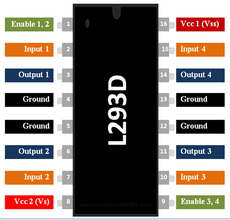
Pin no. 16(VCC 1): This pin is directly connected to +5 volt which is required for its internal circuit of IC . If you are using more than 5 volt you can use 7805 voltage regulator for 5 volts conversion .
Pin no. 8(VCC 2): This pin is connected to voltage source according to your motors voltage requirement . Let us say you are using motor that requires 9 Volt than you have to connect voltage source of 9 volt to this pin.
Pin no. 4,5,12,13(GND): These pins are interconnected internally so no need of attaching all the pins to ground(Zero Volt). You can choose any pin from these 4 pins and connect to ground.
Pin no. 1,9(Enable 1,2 & 3,4): These 2 pins helps us to control the speed of both the motors individually if . Enable 1,2 means this pin(1) have the control over 2 output pins(3,6) means one motor .Similarly Enable 3,4 have control over another motor . When you connect this pins directly to 5 volt than your motor will rotate at its full speed and if you connect it with 2.5 volt than motor will rotate at its half speed and if no voltage is connected to these pins than motor their will be no rotation . And in case of Arduino & microcontroller speed of motors will be controlled with the help of PWM(Pulse width modulation).
Pins 2,7,10,15(Input 1,2 & 3,4): These pins are used to control the direction of motors clockwise as well as anticlockwise. These pins in actual changes the polarity of output pins. And Input 1,2 is for one motor and input 3,4 is for the second motor. Let’s see the truth table it helps you to understand how it changes the direction of the motor
Pin no. 3,6,11,14(Output 1,2 & 3,4): These pins are connected to motors Pin 3,6 to one motor and Pin 11,14 to another one.
| Input 1 | Input 2 | Output 1 | Output 2 |
|---|---|---|---|
| Low | Low | Nil | Nil |
| Low | High | - (GND) | + (Vcc) |
| High | Low | + (Vcc) | - (GND) |
| High | High | Nil | Nil |
Circuit
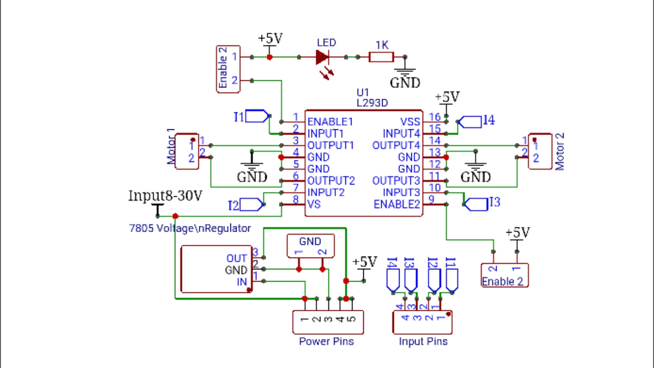
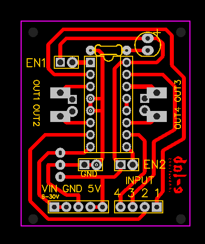
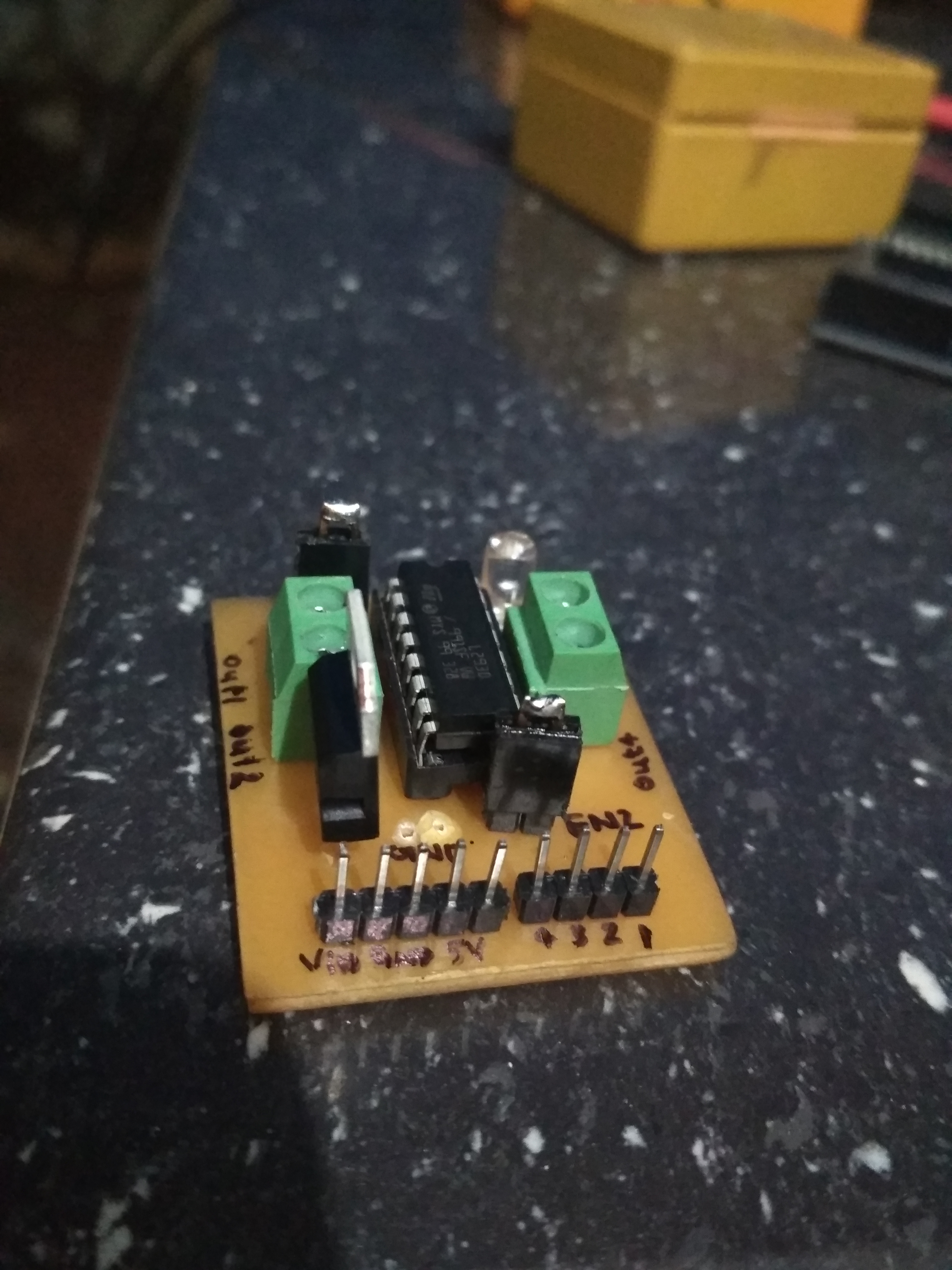
In this circuit, I used 4×1 male header pins for Input, 5×1 male header pins for power supply. We can connect 7-30V to this circuit through IC 7805 voltage regulator or 5V directly. 2 jumper pins are used to connect Enable pins to 5V. You can connect Enable pins to PWM in input by removing those jumper pins. One LED are connected to the 5v through 1K resistor for power indication. The output pins for two motors are taken from corresponding screw terminals.
PCB making
Design PCB board with the schematic diagram
I used Easyeda for design the PCB
Printing
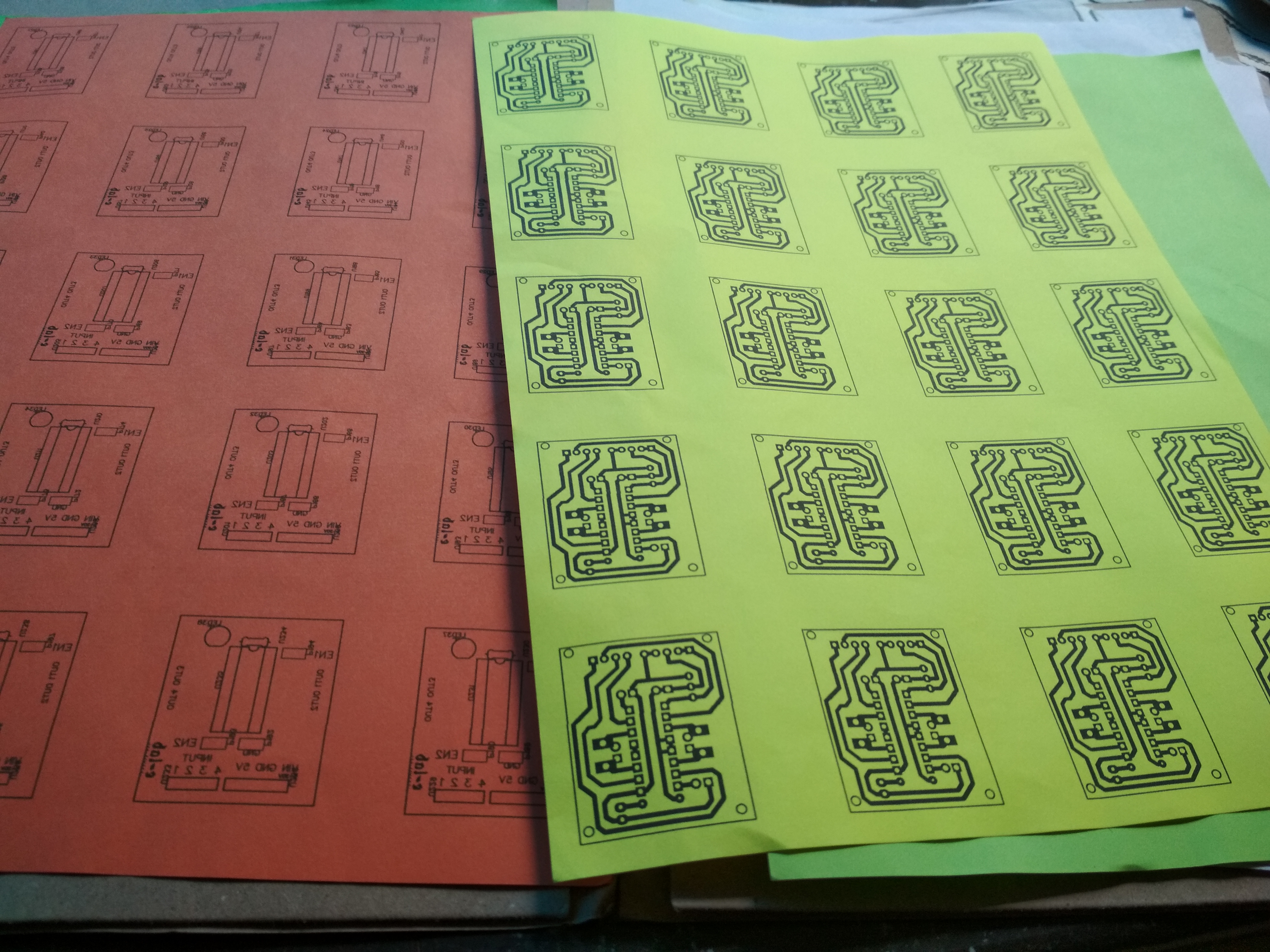
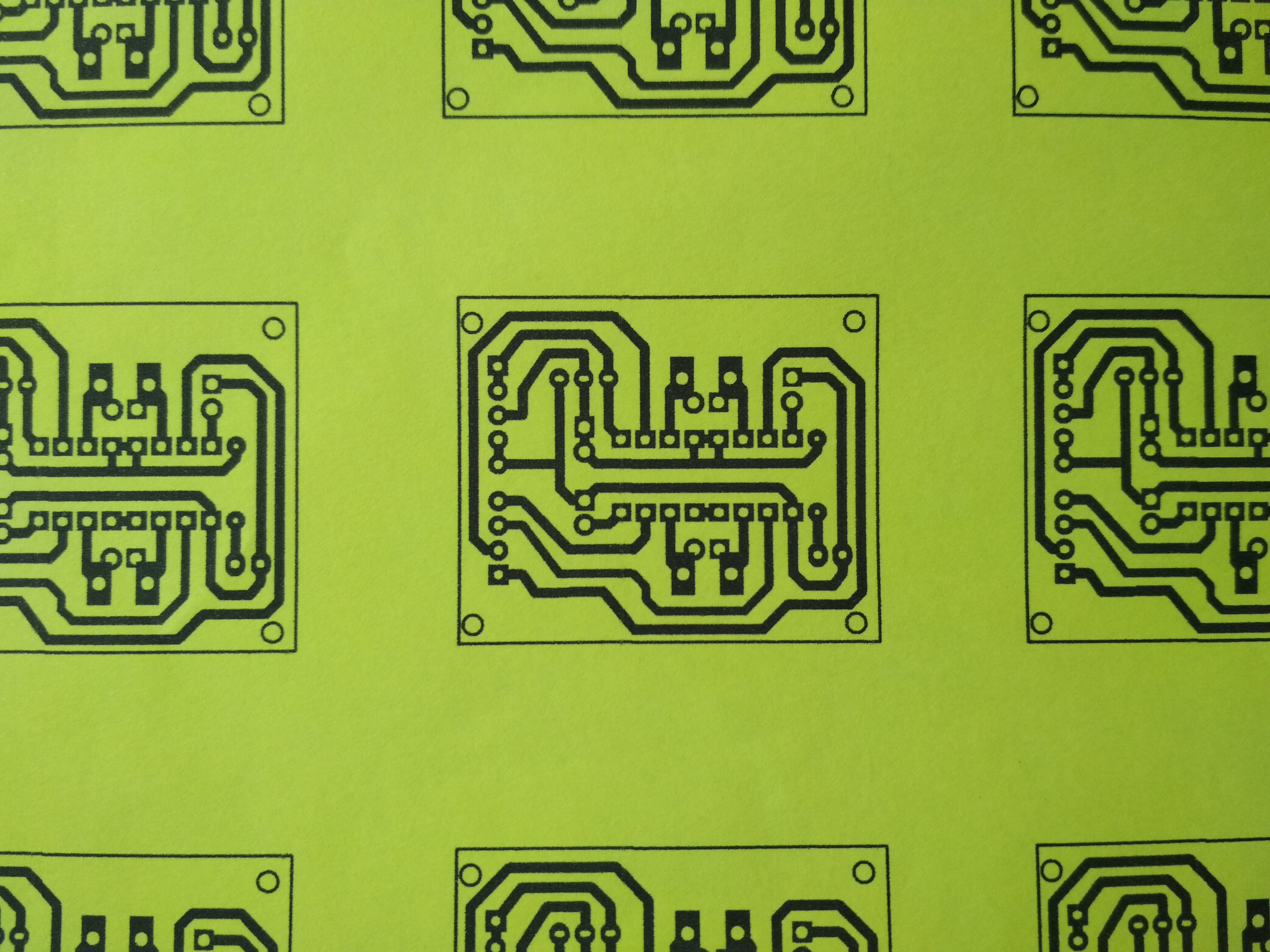
Print PCB layout on the art paper or magazine paper. I used Art paper of size A4.
Use a laundry iron to iron your printed PCB layout to your board. Ironing the printed layout transfers the ink from the paper going to the PCB board. You need to set your iron’s temperature to the highest setting if your paper is thick but if not, set it to the medium setting.
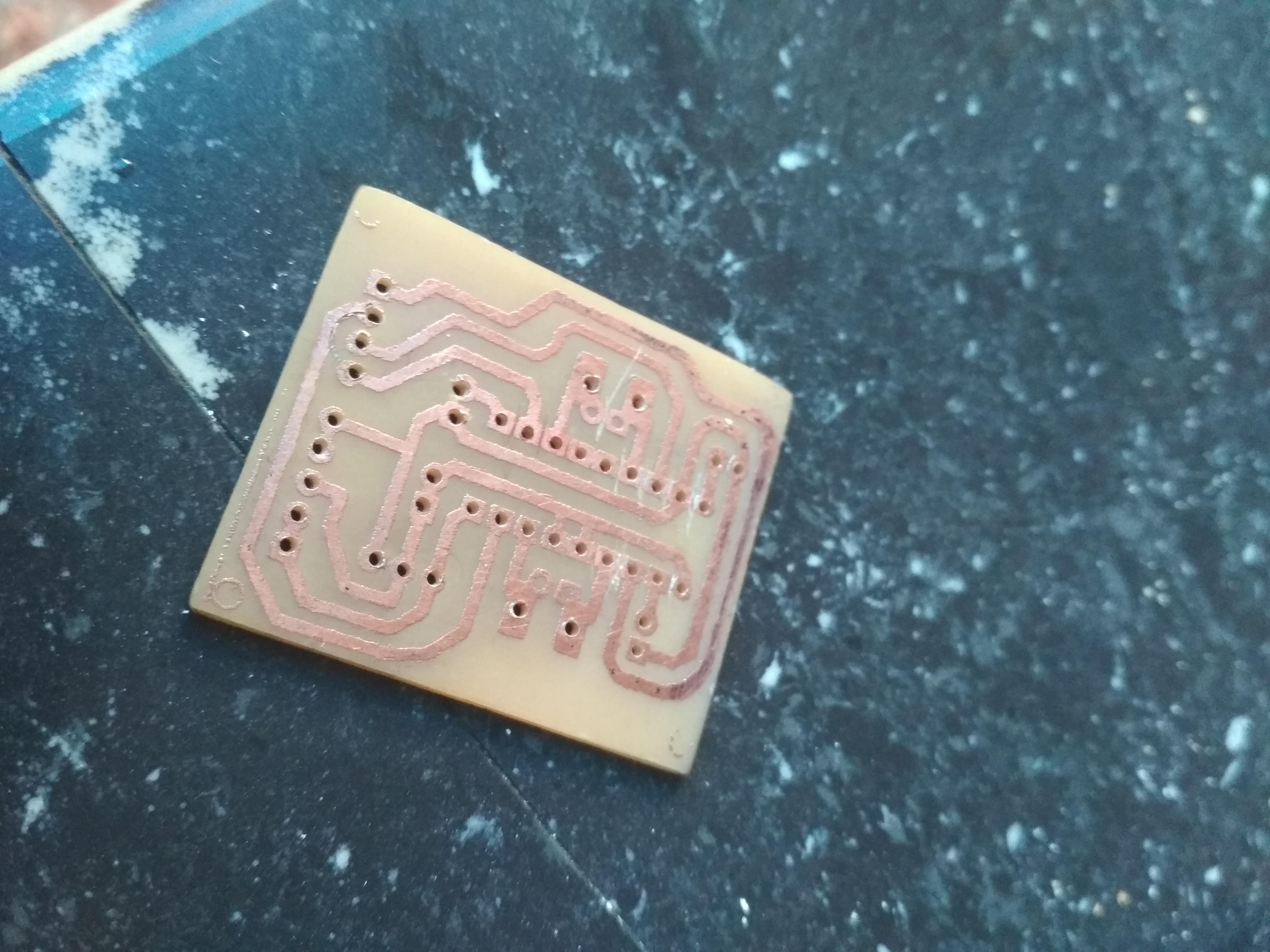
There are different variety of etching solution but the most common is Ferric Chloride. Get a plastic container, never use any kind of metal container. Pour the etching solution on your plastic container. Leave the PCB board for about 30-45 minutes in the container. After for about 30-45 minutes remove it from the container, leaving it for a long time will etch the ink protected area so please remove it when it’s done.
Drill the board with a mini drill a Dremel tool will do. After drilling it rinse it again with water. Be sure to drill it on the copper side, since the copper layout will be your guide where to drill.
Final result
After cleaning all
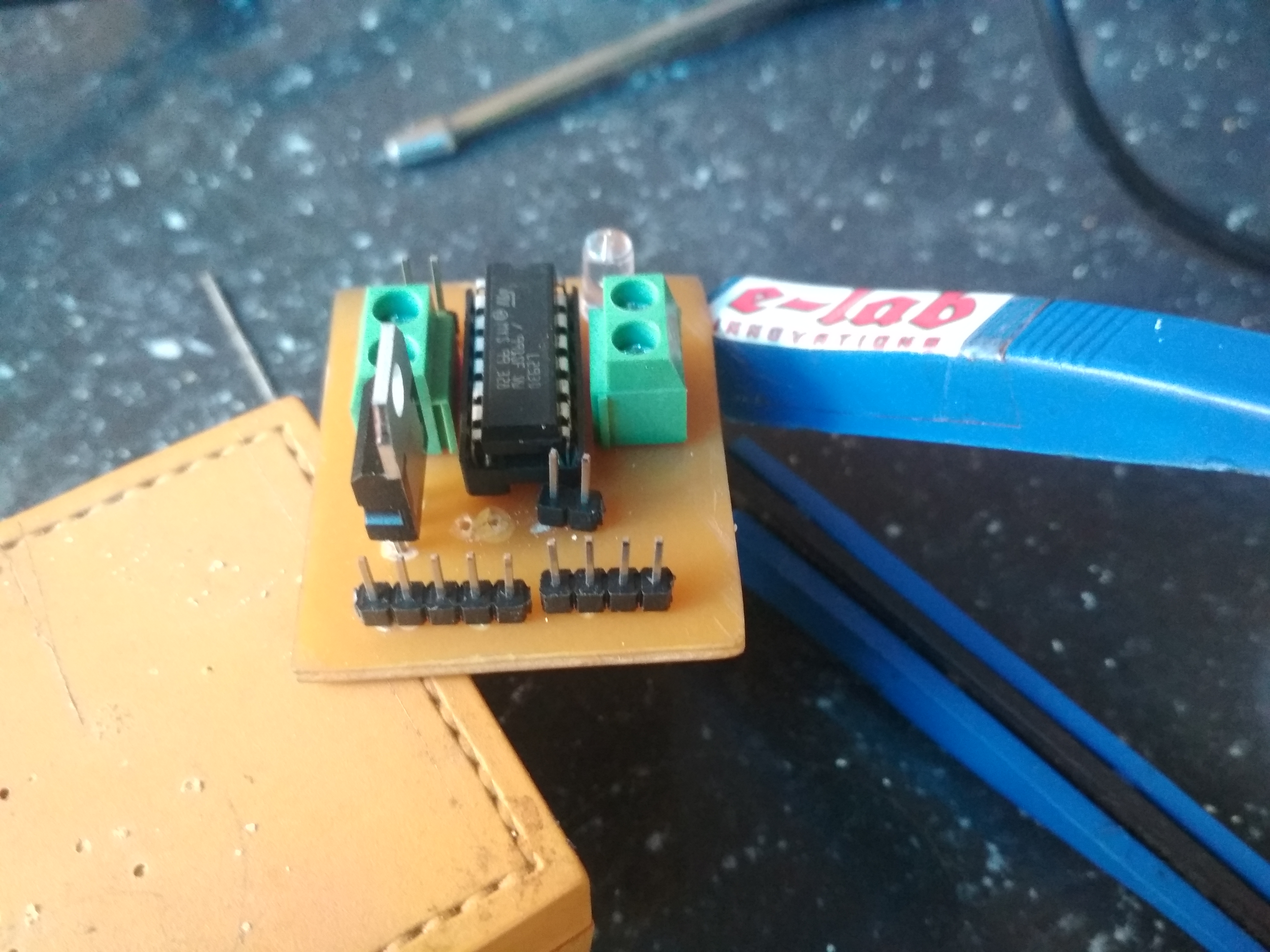
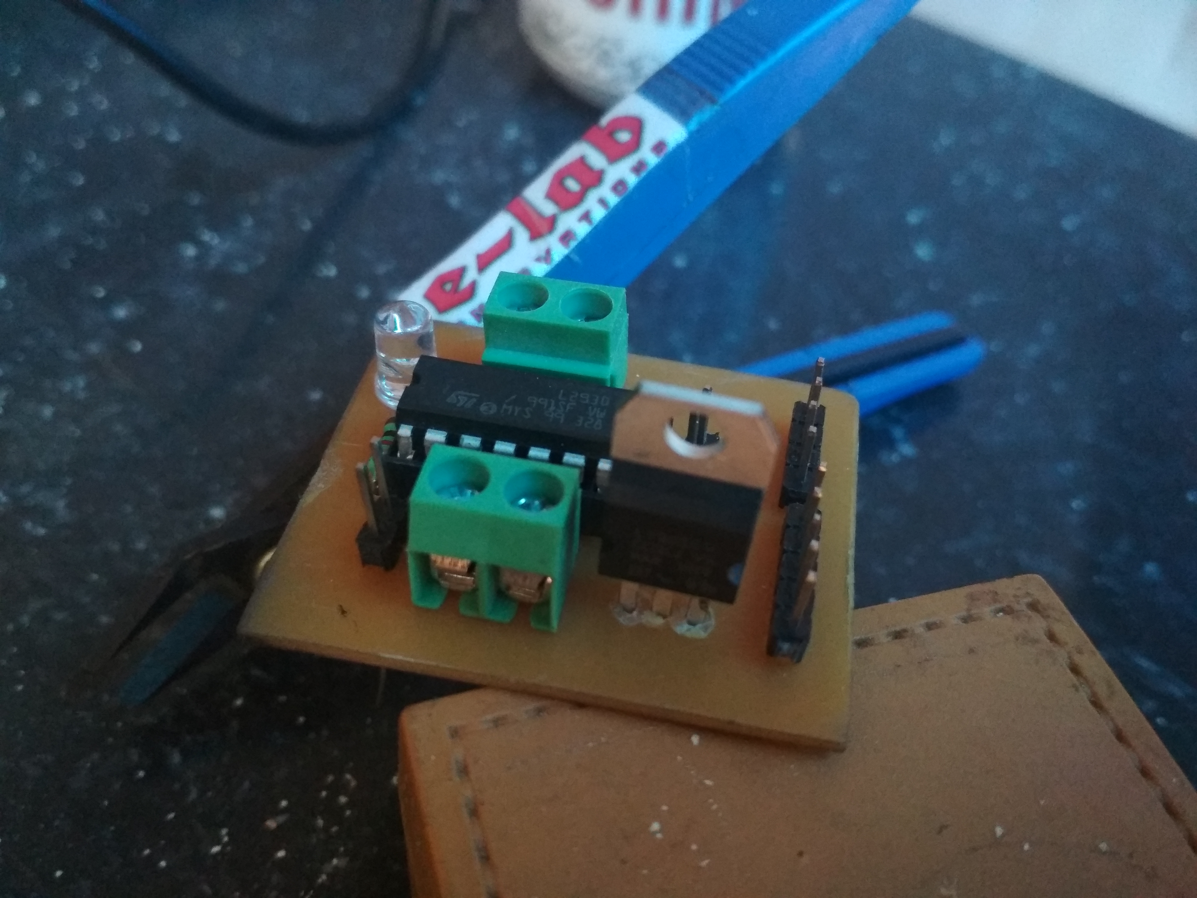
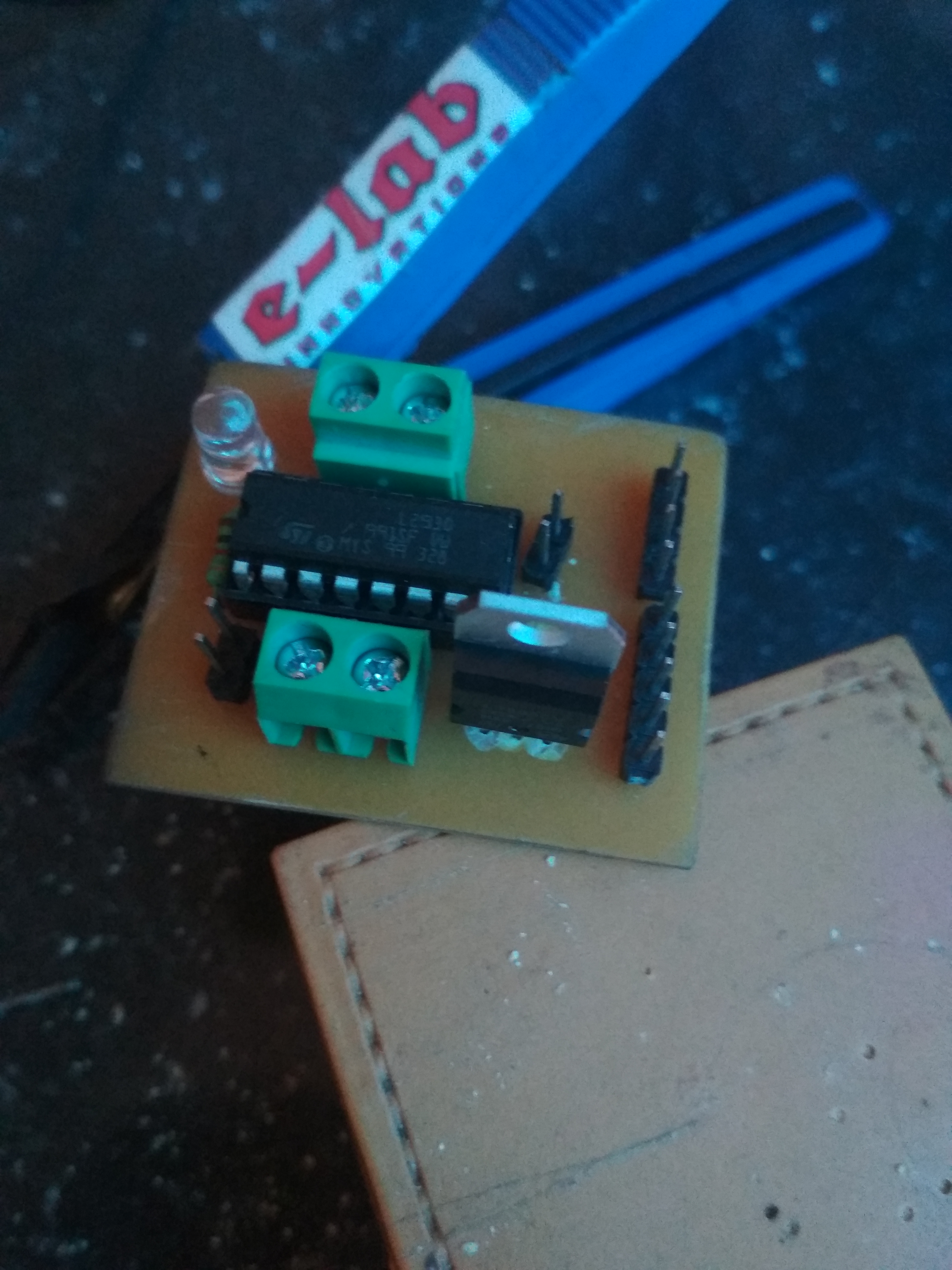
After soldering all components
Using with Arduino
Circuit diagram
Connections
| Motor driver module | Arduino |
|---|---|
| input 1 | D3 |
| input 2 | D4 |
| input 3 | D5 |
| input 4 | D6 |
Code
//this my test code

Comments